

Modern large scale production of urea is based on synthesis from ammonia and carbon dioxide. This process (as originally suggested by Basaroff) was first translated into industrial scale production near 1920 by German chemists in I.G. Farben. The evolution of this original process has been driven by contributions from many countries, and its development continues around the world.
There are two main reactions involved in the synthesis of urea from carbon dioxide and ammonia; the formation of ammonium carbamate (NH2COONH4) from carbon dioxide and ammonia, and the conversion of ammonium carbamate into urea (NH2CONH2).
The reactions involved can be represented by the following equations:
Overall leading to:
The formation of ammonium carbamate (reaction 1) is almost instantaneous and complete between 135 and 200 °C, provided that the pressure of the system is greater than the decomposition pressure of the ammonium carbamate at the system temperature. This formation reaction is highly exothermic; it requires continuous removal of the heat evolved. Ammonium carbamate itself is not suitable for fertilizer application because of its volatility and hygroscopic nature, and because its application leads to crop "burning".
The dehydration of carbamate into urea (reaction 2) never reaches completion. The yield of urea depends on many factors, such as the molar ratio of ammonia to carbon dioxide, the effect of water, reactor pressure, residence time, etc. Reaction 2 is an endothermic reaction; however, the quantity of heat absorbed is much smaller than the heat evolved in the formation of ammonium carbamate (reaction 1). The rate of the urea formation reaction increases rapidly above 160 °C, as can be seen in Figure 1.
The conversion of ammonium carbamate to urea does not go to completion (see Figure 1), so an additional process step is necessary for dissociation and recycle. All processes follow the same general principle: The raw materials carbon dioxide and ammonia enter the autoclave or reactor, sometimes as carbamate already, in which they (further) react and form urea. The reacted mixture then flows from the reactor into a series of dissociation and recycle process steps, operating at consequently lower pressures. In these decomposers the non-converted materials are decomposed and separated from the urea product in the solution. The urea solution is in condition to recover the final product urea. The unconverted ammonia and carbon dioxide recovered from the decomposers are typically recycled back to the reactor to reach complete conversion to urea; this is the principle of the so-called “total-recycle” process. The unconverted ammonia and carbon dioxide are typically recycled back to the reactor by dissolving them into water, forming a carbamate solution, and pumping this carbamate solution back to the reactor. In this way extra water is introduced to the reactor.
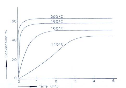
Figure 1: Conversion of ammonium carbamate to urea with time at different temperatures
A greater amount of water in the urea reactor results in a decrease of reactor conversion, as water “pushes” the chemical equilibrium of the overall reaction (reaction 3) to the left side. Figure 2 shows the influence of water (expressed as H/C ratio) on the conversion in the reactor (expressed as CO2 conversion).
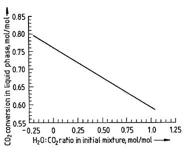
Figure 2: The influence of the H/C ratio on the CO2 conversion.
A higher H/C ratio (more water in the carbamate recycle stream) reduces the conversion in the reactor, leading to a significant decrease in efficiency of the urea process. For this reason it is critical to minimize the water content in the carbamate recycle stream of any urea plant.
The minimum water content required in the carbamate stream is determined by its crystallization point. Thus, as the carbamate solution is pumped back to the reactor, its water content must be at an optimal point. Lower water content can lead to solid formation and higher water content may prevent the urea plant from achieving maximum efficiency.
Achieving this balance is quite complex in practice. Ammonia, carbon dioxide and water can form different reaction products depending on their relative amounts, and each product has a different crystallization temperature. However, an operator’s data is typically limited to a lab analysis of the weight percentages of ammonia, carbon dioxide and water in the carbamate recycle stream. In this case the crystallization temperature level can only be estimated from the amount of water, which is obviously rather inaccurate. Furthermore, the operator needs to take care not to end up in a so-called “water recycle operation mode”, whereby the water recycle in the urea plant is continually increasing and eventually the plant load must be reduced drastically to get out of this mode.
For decades operators have had to resort to their experience in order to run this section of a urea plant smoothly. However, Virtual Materials Group and UreaKnowHow.com have recently joined forces and have been able to address the challenges involved in the prediction of the crystallization temperature of the carbamate recycle stream in a urea plant based on its composition. The results of these efforts will make an operator’s control of the water content in the carbamate recycle stream more effective, which will increase the reliability and efficiency of the urea plant.
Virtual Materials Group Inc. is a global supplier of process simulation software for the oil, gas and chemical industries. Our suite of products includes the fully interactive steady-state and dynamic process simulator VMGSimTMand the industrially proven thermo-physical property calculation engine VMGThermoTM.
VMG's products are backed by an extremely accomplished group of scientists and engineers, dedicated to provide timely and effective world-class solutions.

UreaKnowHow.com is an independent group of urea specialists with an impressive number of years experience in designing, maintaining and operating urea plants. UreaKnowHow.com’s mission is to support, facilitate and promote the exchange of technical information within the urea industry with the target to improve the performance and safety of urea plants.
UreaKnowHow.com is the world’s largest meeting point in the urea industry with engineers & managers from over 95% of all urea plants outside China.
Visit us for more information on who we are and what we can do for you